HDD Geometry 201
Volume 8, Issue # 7 – July 2022
In a previous edition of Inflection Points, we discussed the concept of “setback” and how it relates to the bend radii of drill pipe and well materials. The takeaway from that discussion was the classic 5:1 rule of thumb; namely that to bend the bore profile from a typical HDD entry angle to zero degrees requires ~5ft of horizontal setback for every 1ft of true vertical depth. This basic rule is a great starting point when evaluating the potential feasibility and challenges of HDD at a particular site.
This month, however, we’re going to dig a little deeper into the subject of borehole geometry. Don’t worry; you won’t need your protractor, and there won’t be any complicated equations. Just a general discussion of the concepts at work.
HDD Geometry – Turning in Plan View
One of the amazing features of directional drilling is that we have the power to steer the bit in three-dimensional space. Up, down, left AND right. Almost every HDD bore is going to involve a curve in cross-sectional view; however, many sites will also require curvature in plan view as well. Naturally this added dimension complicates the bore path design.
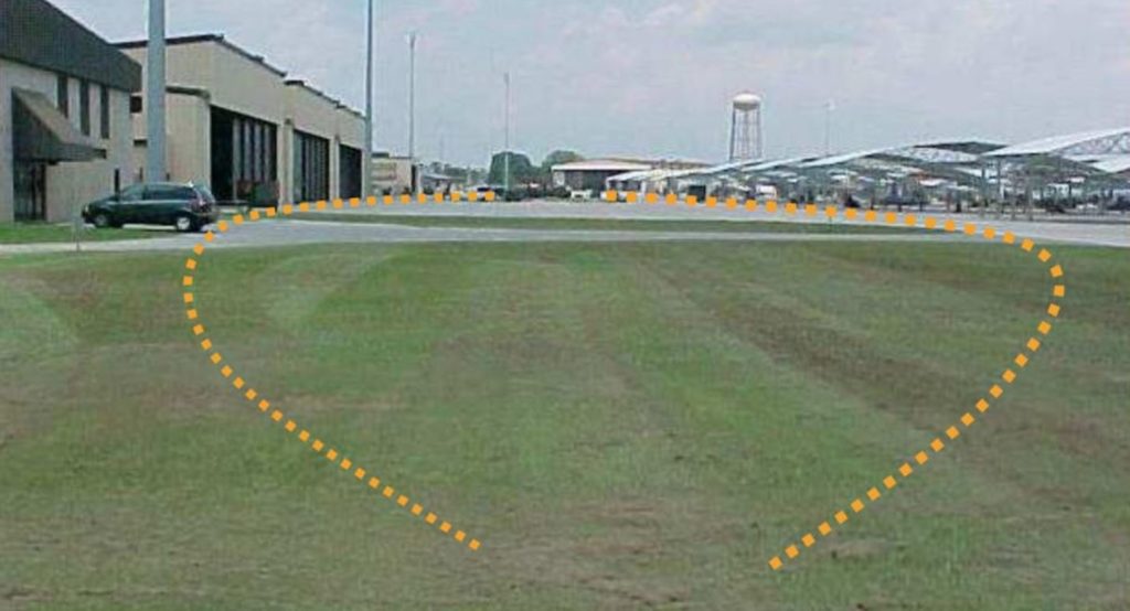
Fig 1: HDD geometry of curves in plan view can be more complicated than straight shots.
Remember that the 5:1 rule of thumb for setback in a directionally straight bore profile was derived from limitations on the effective bend radius of either the drill pipe or the sometimes much-larger well or pipeline that is being pulled in. That radius still serves as the limiting factor when turning in plan view.
Compound Curves Are Complicated
In the case of a compound curve (i.e. turning in cross-sectional and plan view simultaneously like in the depiction above), the pipe is bending in two different directions. Technically, the arc is still only two dimensional, but it has X,Y and Z components when oriented in 3D space. This means the effective radius in any one direction is less than if we were taking on just one direction at a time. There’s only so much “bend” to go around, so the two dimensions have to share what’s available.
Of course, if there’s room, it might be simpler to first execute the curve in pitch (cross-sectional) and then make a subsequent turn in plan view once the target orientation (usually zero degrees off horizontal) has been achieved. Ultimately site-specific conditions and constraints will determine how to best implement these types of complex bore paths.
Pushing Limits
One very important limitation to consider when turning in plan view is that we are limited by a maximum angle off the original trajectory. In other words: we can’t drill in a circle. Sorry.
This limitation results from the attenuation of the rig’s down force. As the bit bends further and further from its original trajectory, more and more of the energy goes into bending the rods through the curve rather than onto the bit face. Eventually so much energy is attenuated that we can no longer get any effective penetration.
Generally speaking, a total bend of ~30 degrees in plan view represents the upper limit of what can be practically achieved. Smaller rigs with more flexible rods can bend more, in theory, but then they also have less power to work with.
HDD Geometry – What to Do About Steep Angles
Although there are some notable exceptions, most standard HDD rigs are designed for a maximum entry angle of between 15-20 degrees off horizontal. Occasionally, we will come across a site where the bore path needs an even steeper pitch. Specialized high entry angle rigs are expensive to operate, and not always the best suited for the site. Often a much more economical option is to use a typical shallow entry angle and then steer “down” to a steeper pitch. We can sometimes use blocking to lift the rear of the rig and increase the entry angle, but worker safety and equipment operating limits then come into play.
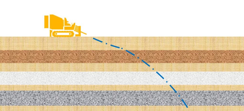
Fig 2: By steering the bit downward, the ultimate bore pitch can exceed the maximum entry angle of the rig.
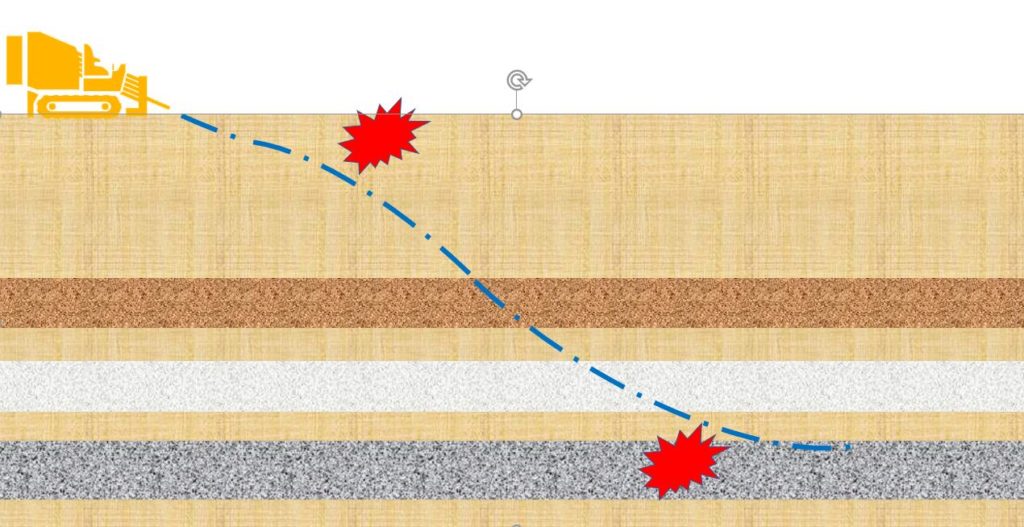
S-Curves Can Be Tricky
Depending on the ultimate bore profile, this approach may draw us in to the allure of S-curve well designs. Although feasible, S-curves can be problematic, particularly in single-ended or blind well configurations.
The challenge is that the inflection points of the S-curve create pinch points of increased resistance. In general, the more complicated the bore profile, the more vigilant we need to be to avoid complications due to well casing failure or borehole collapse.
Very Steep Angles Require Fancy Accelerometers
Another issue with steering downward to achieve steep angles is the limitations of the steering electronics in the bit housing. There are several different steering technologies available, but one thing they have in common is they use accelerometers to measure the pitch of the bit.
Simpler (read: more economical) accelerometers have an effective maximum pitch of 45 degrees. Therefore, the walkover locating systems, which tend to use these more economical components, often have a maximum effective inclination. If the bit were to be turned past the 45 degree mark, we would no longer have an accurate pitch reading.
We occasionally receive requests to use an HDD rig to directionally drill underneath some surface obstruction and then steer down to install a vertical well. Although this is technically feasible with more advanced equipment, the use of those advanced steering technologies like a gyroscope tends to be cost prohibitive.
It’s worth noting that you don’t need to tackle all these nuanced limitations of HDD Geometry alone. You don’t need to run your own bending radius calculations or calculate the attenuation of downforce on the bit. Ellingson-DTD employs a team of highly experienced, qualified professionals who can help come up with a bore plan that is going to work.
Contact us today so we can start collaborating on your project.
Tags: #horizontalwells #geometry #HDD #boreprofile #projectdesign, environmental HDD