Mine Tailings Drain Installed at New England Superfund Site
Late summer DTD completed the successful installation of a gravity drain in a mine tailings impoundment at the Callahan Mine Superfund Site in Maine (see additional info at this link). With recent failures of tailings impoundments, including a significant failure in Colorado during the summer of 2015, regulators are focusing efforts to stabilize, and where necessary, remediate historic mine tailing sites across the country. Many of these impoundments have been filled with unstable slurries of contaminated water and waste rock from the refining process. Typically the impoundments were not engineered for long term stability, and often the tailings are held back by potentially unstable earthen or rock berms. The potential for failure of the retaining structures – under stress from seismic or other loading – could have serious consequences for the downstream ecosystem or residents.
Depending on the remediation strategy chosen, the first step to stabilizing many of these sites is to dewater the impounded sludge. Mine tailings generally have sufficient permeability to allow water to flow through and collect in a gravity drain. However, the potential for initiating a slope or embankment failure due to uncontrolled discharge, piping or other failure mechanisms requires careful consideration of the technology used to place the drain. At the Maine site, boring or trenching directly through the tailings dam was determined to be too risky or even impossible.

Drill site setup in remote location.
For this project, the contracting of DTD to install a horizontal well to dewater the impoundment was the culmination of years of engineering. First, the project team identified potential logistics and mobilization issues related to the remote location and rugged terrain of the site. The second major challenge was to devise an installation method that would minimize the risk of embankment failure, particularly through liquefaction or piping of the fine-grained embankment fill. If attempted improperly, a small localized failure during drilling had potential to create an uncontrolled release of mine leachate, with attendant risks to workers, downstream residents, property and equipment.
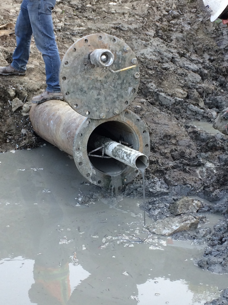
Gravity flow after installation of the drain. (Note: surface casing and blinding flange.)
DTD worked with a local consultant and regulatory agencies to design a unique solution for installing a horizontal drain beneath the embankment. Prior to mobilization, DTD installed a 16″ diameter casing, angled into native soil and rock beneath the tailings impoundment berm.The casing was then pressure grouted in place and a blinding flange (w/relief valve) was welded to the end of the casing. This casing acted not only to stabilize the entry bore, but most importantly, provided a key safety element to prevent an uncontrollable release while drilling upwards into the floor of the impoundment.
The lack of electricity and other services, combined with the rugged and remote terrain made a gravity drain a design necessity. Drilling began down gradient of the toe of the embankment. As the bore advanced, the drill string was steered beneath the clay embankment and then up into the lower levels of the impoundment. The drain trended at an ~1% slope to facilitate gravity drainage of the impounded leachate and water, while controlling flow velocities to prevent erosion within the embankment or piping of solids. Minor discharges of waste water were seen throughout the drilling process and after two days, drilling was completed to a total drain length of 991′.
To optimize the amount of well screen in contact with the target zone of saturated tailings, this drain was completed as a single ended installment. DTD employed our patent-pending Knock-Off drilling technology to place the well screen. PVC well materials were inserted through the drill rods to disengage the sacrificial drill bit used with our Knock Off technology drilling assembly. The drill rods were then retracted, allowing the tailings to collapse around the newly installed drain.
Following installation, the drain was developed by flushing and jetting to remove residual drilling fluid. An annular grout seal was placed around the PVC drain materials to keep liquid from bypassing the drain. The drain was tested to see it was draining the fluid from the impoundment and then capped. Once a water treatment system is constructed to treat the discharge water, the drain will be put into use.