Horizontal Well Geometry 101
Volume 8, Issue #2 – February 2022
In this month’s newsletter we’re going to cover some basic principles of horizontal directional drilling (HDD) borehole geometry. HDD provides an incredible amount of flexibility with regards to bore profile design and horizontal well screen placement. But there are limitations, and practitioners need to understand some basic principles of HDD in order to work around those limitations.
Principle #1 – We can only turn so sharply
The middle “D” in HDD stands for directional and means that the driller can steer the bit in any direction: up, down, left or right. However, any turn or bend in the bore path is limited to a gentle arcing curve vs a sharp bend. There are a couple reasons for this.
First, the steering mechanism relies on an asymmetrical down-hole assembly. In other words: the bit is bent. As drilling progresses, the driller exploits this asymmetry to deviate the bore path in the desired direction. But it’s a very slight bend, which means the deviation is also very slight.
As much as we’d like to, we can’t make a 90 degree turn over a distance of a few feet. It’s simply not possible when the bend in the down hole tooling is only 2 or 3 degrees.
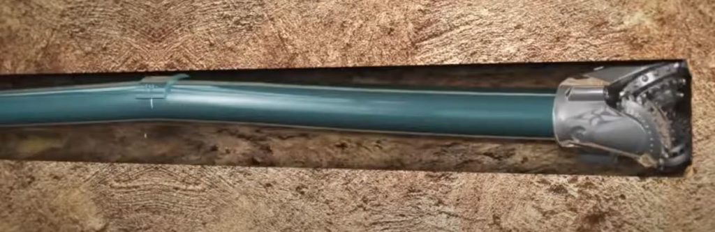
Fig 1: Graphic representation of a directional drilling “bent sub”
Second, the elasticity of steel drill pipe limits the minimum bend radius of a turn in the bore profile. Most people don’t think of steel as being a particularly flexible material, but in pipe form it can bend substantially before it permanently deforms. However, with a tight enough bend radius, it will deform permanently (or possibly break), and this is no bueno for an HDD operation.
Minimum Horizontal Setback
The most common way that these turning limitations in a bore profile frustrate well designers is the need for minimum horizontal setback. Property boundaries or physical obstacles at the surface (like buildings or other infrastructure) often restrict the drill rig set up location. But depending on the depth of the subsurface target there might not be enough setback distance.
When we talk about horizontal setback, we’re referring to the distance from the bit entry location to the point where the bore profile levels off to zero degrees (horizontal) at a given depth. If we could turn sharper, we could reduce the setback, but we can only turn so sharply.
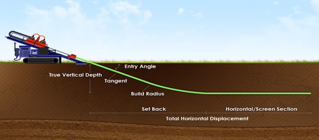
Fig 2: Horizontal setback is a key variable when designing an HDD bore profile
Minimum setback (expressed as a ratio of horizontal length to vertical depth) can vary from 3:1 to as wide as 6:1 or 7:1. The precise amount of minimum setback required depends on several different factors, which we will discuss in more detail in a future newsletter.
Principle #2 – We’re not vertical drillers
Directional drilling in the oil and gas exploration industry involves setting up big powerful rigs at the surface with a vertical entry angle. They then proceed to drill very deep, usually thousands of feet before deviating directionally. But HDD is different.
The “H” in HDD stands for “horizontal”, and although the oil guys eventually get to horizontal, they start out at 90 degrees, and spend a lot of time drilling vertically.
In addition to asymmetry, down hole directional drilling tooling will have steering electronics which track the bit’s position in three-dimensional space relative to the planned bore path. Without going into too much detail, steering electronics that can function at a complete range of pitches (between 0 and 90 degrees) are extremely expensive and complicated to operate. This means that the O&G boys have them but we humble HDD contractors don’t.
Most HDD tooling operates with a maximum 45-degree pitch. If the bore profile gets any steeper than that, the electronics will not operate reliably.
Since our tooling doesn’t really work at steeper angles, HDD equipment typically has a maximum entry angle of 6-20 degrees. There are a few rig platforms that are capable of steeper entry angles. Some even go all the way up to vertical. However, they are specialty platforms that can be very challenging to operate.
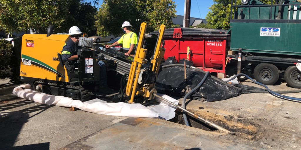
Fig 3: An HDD rig set up at typical entry angle of 15 degrees off horizontal
The tooling configuration for a vertical entry angle is very different from a shallow horizontal entry angle. So, for the most part, the different orientations are an either-or choice.
There are a number of reasons why one might want to design a directional bore profile with a steep pitch (either with near-vertical entry or a shallow entry angle that turns downward). It’s important to understand that this design element might not be achievable with standard HDD equipment.
Principle #3 – We can’t drill in a circle
Nearly all non-vertical wells that we install are designed with an ending pitch that is different from the original entry angle (often zero degrees or “horizontal”). In other words, the bore profile will require “up/down” steering.
But many projects will also require “left/right” steering. This ability to turn in “plan view” is incredibly powerful when designing bore profiles for horizontal wells. We often use this design element to overcome surface obstacles that would otherwise cause horizontal setback issues. Alternatively, it is great for coaxing the wellhead position to be closer to the treatment system or co-locating several wellheads into a single vault, reducing infrastructure costs.
However, many designers will get a little carried away with the total left/right turn. In addition to limitations on how sharply we can turn, we’re subject to a maximum total left/right deviation as well.
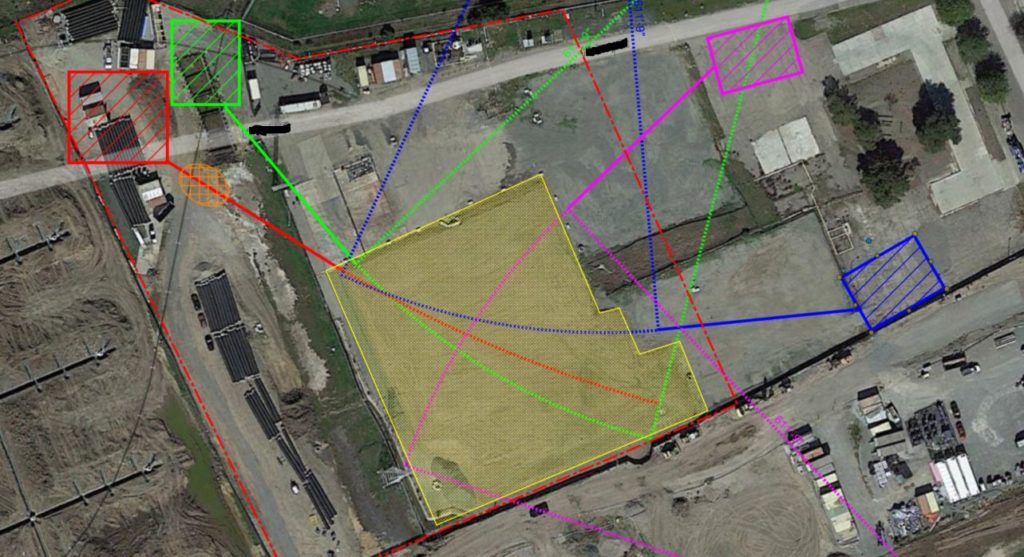
Fig 4: Diagram evaluating different well screen placement options within a target area (yellow shade) given the limitations of possible rig set-up areas, bend radius and total lateral deviation.
The reason for this limitation goes back to our shallow entry angle. In a vertical rotary bore, gravity supplies much of the force on the drill bit. Steel is heavy and the weight of the tooling adds up. That weight contributes much of the energy required to penetrate the geology.
Putting left or right steer into a bore does not get any beneficial “push” from gravity. This means all of the force on the bit comes from the hydraulic power of the rig.
As the bore profile turns and the new heading deviates more and more from the original alignment of the rig’s power, the pushing force of the rig is attenuated by the curvature of the pipe. Eventually this attenuation takes up most of the rig’s energy, and the penetration rate falls off a cliff.
We’ll dive deeper into the concept of turning in plan view in a future article. But for now just understand that the maximum total deviation left or right of the original alignment is ~30 degrees. Note that this is a cumulative limit. You can use up the entire deflection in one turn, or dole it out along the profile in multiple deviations.
Conclusion
HDD bore profiles can get pretty complicated. Understanding the basic principles that govern the geometry is important for designing wells that can feasibly meet project objectives. We intended this introduction to cover just a few basic first principles. There’s a lot more detail that’s worth diving into. So keep an eye out for more advanced articles in the future.
Of course, if you ever need assistance designing a horizontal well project, we’re happy to help.
Tags: #horizontalwells #geometry #HDD #boreprofile #projectdesign